
1403 Project Background
April 10, 2017
The 1403 family was IBM's flagship line of printers in the 1960s, supporting the permanent record needs of the 1401 system at 600 lines per minute, and the System/360 at 1,100 lines per minute. The System/360 high speed printer was known internally as the 1403-N1.

The printer is an electro-mechanical unit. Controls for the 1403 family of printers were provided by circuitry within the data processing system, not the printer. A plethora of printer controllers were tailored for each of the CPU-Printer combinations. With the advent of the System/360, the CPU interface became standardized and the 1403-N1’s printer controller moved to a separate unit, the IBM 2821. It used IBM's first generation printed circuitry — Standard Modular System (SMS) cards, which consisted of discrete transistors, resistors, capacitors, and other components mounted on single layer printed circuit boards. Circuit cards controlled the timing of pulses that energized the printer hammers for about 1.2 milliseconds in duration, a critical parameter for high quality printing. The 2821 also contained power supplies to drive the hammers, buffers to hold the print data, and additional electronics to interface to the host computer.

Driving the hammers in the 1403-N1 are circuit cards that produce a 60-volt, 5-amp electrical pulse to energize the hammer magnet coil, throwing the hammer forward to push the paper into the ribbon and onto the passing type slug.

The critical components of the 1403-N1 printer are the printer train, containing the type slugs, and the hammer driver units that push the paper and ribbon onto the print slug producing a character impression on the paper. The print train consists of three-character type slugs riding on a machined rail. The spacing from character to character is 0.1505”.

The print train can print a line of text consisting of a maximum of 132 characters at a rate of 1,100 lines per minute. The print train continuously moves within the machined rail at a speed of 206.4” per second (~12 miles per hour). In order to register each printed character in the correct horizontal placement, the timing of when to energize a hammer to print a character on the paper must be made within a 5 micro-second window.
Here is the schematic of the hammer driver that, when energized for 1.2 milliseconds, impacts the paper against the ribbon and slug on the print train that results in a printed character.

In 2013, members of the TechWorks! Vintage IBM Computing Center (VICC) were asked if they would accept the challenge of revitalizing an IBM 1403-N1 printer that had been in storage for more than 25 years. The challenge was accepted and revitalization of the IBM 1403-N1 printer began in Spring 2013.
The printer was received in reasonably good condition, but without the required printer controller. A world-wide search for a vintage 2821 resulted in only sparse documentation of the device. The printer mechanics required only cleaning, new lubricants, and a new ribbon, with one exception — a missing idler gear. A mechanical engineer from the original 1403-N1 design team took responsibility for replicating the gear in heat-treated steel, specified with advice from the Computer History Museum's IBM 1401 team. Print hammer and hammer magnet units were opened, inspected, and components tested for independent movement. The hammers responded appropriately to activation pulses without intervention. The A/C motors driving the print train, the hydraulic unit, and cover raise/lower mechanism were returned to operation.
With the electro-mechanical components of the printer in operational condition, we turned to the electronics needed to drive the printer. Rather than recreate the 2821 design in 1960s technology, the VICC team chose to re-implement the functions using today's electronics, packaging, and software.
Building the Printer Controller Part 1: 2013-2014
With the electro-mechanical components of the printer in good condition we turned to the electronics needed to drive the printer. The IBM 2821 Controller provides the electronics that interfaces the 1403-N1 to a System/360 or System/370 CPU. A world-wide search for a vintage 2821 resulted in only sparse documentation of the device. In the absence of an extant IBM 2821 printer controller and with minimal documentation of the 2821 logic and functions available, the VICC 1403-N1 team chose a two-pronged approach — conserve the vintage mid-20th century printer and reverse engineer a controller in 21st century hardware and software to drive it.
To meet the challenge of bridging sea changes in technology, the VICC organized a team in the Summer of 2013 to develop the printer controller. The Center recruited a team spanning 20-75 years of age from the community surrounding IBM Plant #1 in Endicott, NY. Three generations of computer professionals were essential to the success of the IBM 1403-N1 revitalization strategy. IBM Endicott engineers whose careers spanned the 1950s -1980s, well-versed in electro-mechanical systems and discrete circuits, provided in-depth understanding of the original printer design, as well as rare documentation from personal archives. IBM Endicott and Lockheed Martin Owego veterans, whose careers spanned 1970s-2010s, used their expertise in integrated circuits, packaging technology, and control of electro-mechanical equipment to micro-second timing requirements to reverse-engineer the 2821 logic in 21st c. hardware. They also helped bridge the terminology gap between the team's 1960s design engineers and today's student engineers. Students in their final year (2013-2014 academic year) at Binghamton University's (BU’s) Watson School of Engineering delivered software and hardware for microprocessor control of the printer sub-system, and built a user interface on a host personal computer to control printer operations. Triple Cities MakerSpace (TCM) designed the hardware chassis, built custom circuit card holders using 3D printers, and software for the custom circuit cards. By tapping multi-generational talent to each contribute their areas of expertise, the synergy of idea exchange between the generations was palpable, expanding insights of all team members and effecting knowledge transfer across the decades.
TechWorks! volunteers who participated in the design of the 1403-N1 printer worked with the BU students to understand how the printer worked and what hardware and software was needed to make the printer operational. The team developed the following System Configuration that divided the project effort into three parts:
Personal Computer
The Personal Computer consists of a PC running Windows. A Windows-based User Interface (UI) provides a simplified method of creating a text file that is printed on the 1403-N1 printer. The UI also controls the operation of the Printer Controller Box. The software is developed by the BU student team.Printer Controller Box
The Printer Controller Box emulates the functions of the IBM 2821 needed to operate the 1403-N1. The Printer Controller Box senses the Sync Pulses from the 1403-N1 to determine the position of the characters on the print train. Based on the text input from the PC, the Printer Controller Box determines the sequence of commands to the Hammer Driver Cards that energizes the hammers that results in the printing of a line of characters and the Carriage Driver Card that controls the vertical line spacing. This Printer Controller Box is designed and built by the BU student team.1403-N1 Printer
Refurbished by TechWorks volunteers.

The design and development of the Printer Controller Box required the combined efforts of the TechWorks! volunteers who understood the operation of the 1403-N1 printer and the BU students who designed and implemented the hardware and software. Accurately printing a character in a specific position on the paper with the print train moving at 206.4” per second requires firing the print hammer with micro-second accuracy. In order to determine if the hardware and software could achieve the micro-second timing accuracy needed, a prototype of the Printer Controller was developed before a full scale version was built.
A picture of the prototype Printer Controller Box shows the hardware components enclosed in a plastic chassis. A chipKIT™ PRO MX4 microprocessor implements the software that interfaces with the PC on one side and the Hammer Driver printed circuit boards (PCBs) and the Carriage Driver PCB on the other. The chipKIT™ software accepts text and control commands from the PC and generates signals to the Hammer Driver and Carriage Driver cards that send the signals to the 1403-N1 to fire the hammers and control vertical line spacing. The print hammers on the 1403-N1 require a 60 volt pulse with a duration of approximately 1.2 milliseconds. In the prototype, two Hammer Driver PCBs were built with each PCB capable of driving 6 hammers. The Carriage Driver PCB also generated the 60 volt signal needed to control the line spacing mechanism. All of the software to fire the printer hammers and provide carriage control was implemented in the chipKIT™ PRO MX4. In the picture is also an Arduino micro-processor that was used for testing purposes.
The design and testing of the Hammer Driver and Carriage Driver PCBs was completed successfully as was the wiring between the chipKIT™ and PCBs. The design and implementation of the software turned out to be more complex than anticipated. There are two key algorithms that the software needed to implement. The first is to determine which hammer to fire. Due to the physical relationship of the characters on the print train and the printer hammers, the selection of the hammer to fire on a line was non-trivial. Secondly, because the print train is constantly moving at 206.4” per second, determining when to fire the printer hammer required determining to micro-second accuracy when a character on the print train is in the correct print position. By April, 2014, the team was partially successful in implementing the software to correctly time the firing of the printer hammer.

Building the Printer Controller Part 2: 2014-2015
During the summer of 2014, the TechWorks! and Triple Cities Makerspace (TCM) volunteers put together a plan to develop the “production” printer controller based on the lessons learned from the prototype built with the BU students during the 2013-2014 academic year. We again planned on recruiting a team of BU undergraduates to be part of the team. The TechWorks! and TCM volunteers would focus on the printer controller chassis and electronics and the BU undergraduates would focus on the user interface and printer controller software.
Chassis and electronics: TCM undertook the design and fabrication of the chassis. The chassis houses a 200 MHz chipKIT™ Wi-Fire microprocessor that accepts commands and data from the Windows-based PC and controls the Hammer Driver and Carriage Driver cards. The Hammer Driver and Carriage Driver cards were based on the design of the prototype printer controller. Several improvements in design were made.
The cards were modified to include an Atmel ATMega328P chip that implemented the precise timing requirements for firing the printer hammers under command of the software in the chipKit™ and thus simplified the control software in the chipKit™.
The cards were modified to drive 8 hammers versus 6 and the electrical design was cleaned up.
TCM designed and 3D-printed the custom card holders in ABS plastic to mount the Hammer Driver and Carriage Driver Cards in the chassis.
The picture below presents a side-by-side comparison of advances in electronic packaging in the last half century. The circuitry on the SMS card drives two printer hammers but the timing circuitry is implemented on a separate card. The circuitry implemented in modern technology supports 8 printer hammers along with the timing circuitry.

This is a photo of the chassis populated with Hammer Driver and Carriage Driver cards slotted into the blue 3D-printed card holders.

Software: There are three software components that implement the printer controller.
The User Interface is implemented in the Windows-based Personal Computer.
Control of the printer controller and determining the hammer and carriage control firing sequence is the responsibility of the chipKIT™ software.
Firing the printer hammers with micro-second accuracy is performed by the Atmel ATMega328Pchip that resides on each of the Hammer Driver cards.
The User Interface software and the printer controller software in the chipKIT™ were developed by the BU students. The Atmel chip software was designed and implemented by a volunteer from TCM and both the BU students and TCM worked together to ensure that all the software worked together.
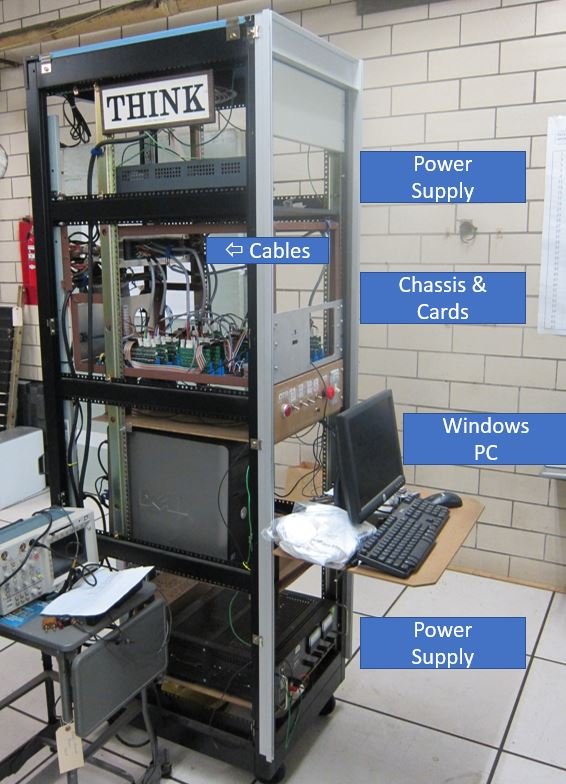
The complete Printer Controller is housed in a standard 19” equipment rack. At the bottom, an adjustable lab power supply provides +60 volts for the hammers, and a contactor to control the 3-phase, 208V input for the printer’s AC motors as well as the single-phase 120V feed to other system components. A tray above the power supply holds the personal computer that implements the UI. At eye-level (for visitor viewing), is the chassis to hold the driver cards and cables to interface with the printer. The top tray has a power supply that provides +5 volts to the chipKIT™ and to the Atmel chip/other logic on the hammer driver cards.
A view of the back of the rack shows the two thick grey cables from the printer terminating in the block of vintage SMS connectors. The SMS connectors interface to connectors on the opposite side that connect to the Hammer and Carriage driver cards.

Over more than two years many volunteers and BU students worked on the revitalization of the System/360 1403-N1 printer. On March 9, 2015, a small subset of the team came together to complete the integration of all the hardware and software and make the first attempt to print in many years. A summary of that day is provided in the hyperlink below. The team that worked that day were Nick Hekman and Alena Yampolskya (BU WCP students); Don Manning, Art Law, and Bob Lusch (TechWorks! volunteers); and Susan Sherwood (CT&I director).
The team’s successful revitalization of the S/360 printer was celebrated publicly on May 16, 2015, as part of the Binghamton University graduation activities for the second group of Watson School seniors. In the photograph below there are representatives of the BU student teams of 2013-2014 and 2014-2015, IEEE Binghamton Section, TechWorks! volunteers and advisors, and Emerson Pugh who was the guest speaker at the celebratory event. The action debut event — Before Silicon Valley, there was IBM Endicott & IBM Owego — featured printing of 16 characters per line.

Since then, work has continued to further tune the software, install more hammer driver cards to add more print columns, and improve the chassis for better accessibility and visibility. The system is demonstrated for TechWorks! visitors, who receive souvenir banners that they watched being printed.
In May 2017, the National Museum of Computing and the BCS Computer Conservation Society in the United Kingdom held a joint two-day meeting "Making IT Work" on the practice of computer conservation, bringing together worldwide experts in computing and software conservation. The TechWorks! System/360 printer revitalization project was awarded second place among projects submitted from across the world. The following paper submitted to the "Make IT Work" conference contains additional information on the project.